 | 16 Jul 2018
Monitoring of the gas composition and stable carbon isotopes during side track drilling in Ktzi 203 at the Ketzin CO2 storage pilot site, Germany
Alexandra Szizybalski
Ben Norden
Andrea Vieth-Hillebrand
Axel Liebscher
the Ketzin Group
Between 2004 and 2017 the storage of CO2 in a deep saline aquifer was investigated in detail at the Ketzin pilot site close to Berlin. The series of research projects, coordinated by the GFZ German Research Centre for Geosciences, also incorporated an interdisciplinary scientific monitoring program during all phases of the storage process which provided a reliable insight into the overall behaviour of CO2 during storage in the underground.
Prior to abandonment and cementing of the Ktzi 203 observation well, two side tracks were cored from 643.1 to 662.6 m and from 624.5 to 654.5 m, respectively. The drilled sections included the transition zone from the cap rock (Weser Formation) to the reservoir in the Stuttgart Formation which had been exposed to the injected CO2 for more than nine years. During the drilling operation continuous mud gas logging was performed by applying a mud gas separator, a mass spectrometer and a CO2 isotope-analyser for continuous separation and analyses of the extracted gas. Drill cores were shrink-wrapped with plastic foil to collect discharging gases.
CO2 concentrations in the cap rock were relatively low and their isotopic compositions were in accord with typical Upper Triassic formation fluids providing no evidence for a significant CO2 infiltration from the underlying reservoir into the cap rock. A clear increase in the CO2 concentration and a shift in between the cap rock and the reservoir indicated the presence of the injected CO2 in the sandstone formation. The comparison with samples collected five years earlier in 2012 showed similar concentrations and isotopic depth trends which indicate a rather stagnant CO2 plume at depth and the tightness and integrity of the cap rock and the borehole cementing.


Within the framework of several international and national research projects, the GFZ German Research Centre for Geosciences coordinated an in-depth study on the geological storage of CO2 over a total period of 14 years encompassing a comprehensive operational and scientific monitoring program of the reservoir, the above-zone and the surface at the Ketzin pilot site located approx. 40 km west of Berlin. Details of the monitoring concept are given e.g. in Giese et al. (2009), Martens et al. (2013).
The test site is located at the southern flank of the Roskow-Ketzin double-anticlinal structure formed above a deep-seated Permian salt pillow. Upper Triassic fluvial channel facies sandstones (Förster et al., 2006) serve as reservoir rocks overlain by more than 165 m of muddy cap rocks.
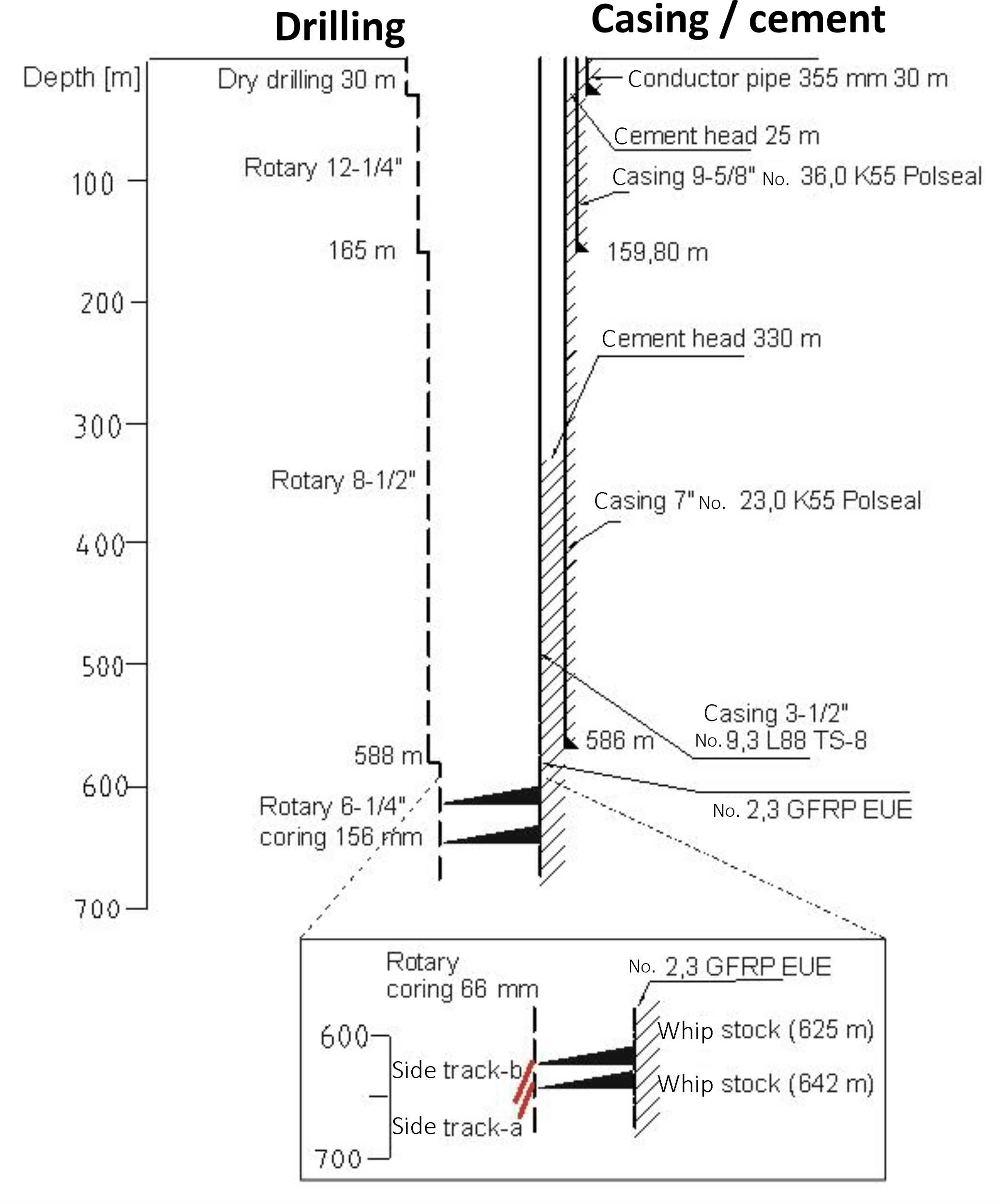
Beginning with an exploration phase in 2004, drilling of the first three wells took place in 2007 followed by the injection of about 67 kt of CO2 into the saline aquifer reservoir at a depth of 630 to 650 m starting in June 2008 (Martens et al., 2014; Wipki et al., 2016). For above-zone monitoring in 2011 a shallow well was drilled to a depth of 446 m into the Exter Formation, the first aquifer above the cap rock. In 2012 a further deep well (Ktzi 203) was drilled at a distance of about 20 m from the injection well into the reservoir formation to sample rock material and fluids which were in contact with the injected CO2 for more than four years. The injection ended as planned on 28 August 2013 followed by dismounting of the injection facilities at the surface and the in-part backfilling of the observation borehole Ktzi 202 with CO2 resistive cement. Based on the abandonment schedule, the opportunity was used to drill two side tracks in the Ktzi 203 observation well in September and October 2017 prior to the abandonment and cementing of the well. In preparation for the side track drillings, two whip stocks were installed in the GFRP (glass fibre reinforced polymer) casing of the borehole at a depth of 642 and 625 m, respectively (Fig. 1). As the whip stocks were not orientated, the direction of the side boreholes was random. The determination of the track direction was possible only in the deeper hole which had an inclination of 1∘ in a WNW (∼285∘) direction. The side tracks were drilled from 643.1 to 662.6 m (track-a) and from 624.5 to 654.5 m (track-b) respectively with about 93 % core (36 mm diameter) retrieval. The drilled sections included the lower part of the cap rock, the transition zone and the main storage reservoir in the upper Triassic Stuttgart Formation which had been directly exposed to the injected CO2 for more than nine years.
For the two side tracks, different drilling muds were used. The drilling mud used for hole-a was based mainly on a NaCl salt solution whereas the drilling mud of the second side track (hole-b) was based on potash (K2CO3), the same mud as applied during drilling and coring of the Ktzi 203 main borehole in 2012, allowing a direct comparison of the actual measurements with the results obtained five years earlier.
During the drilling operation continuous mud gas monitoring and gas chemical investigations were performed to provide background information on the CO2 gas content in the pore spaces and in the formation fluids of the cap rock, the transition zone and the reservoir as well as to characterize its isotopic composition and to trace the migration and the spatial fate of CO2 in the subsurface. We present here the data obtained from measurements performed within the two side tracks drilled in 2017 at Ktzi 203 and compare the results with similar measurements on CO2 concentration and carbon isotope ratios collected in 2012 from the same depth section. In doing so, we can provide reliable information on variations in both the thickness and in the prevailing gas concentrations of the CO2-bearing layer over the last five years.
The side cores were drilled with a conventional workover drill rig Cabot Franks 500 with a mud circulation rate of 200 L min−1. The main functions of the drill mud is to provide hydrostatic pressure in the bore hole, to cool the drill bit while drilling and to extract drill cuttings as well as all gases entering the bore hole at depth. For the extraction of the gases dissolved in the drill mud a conventional gas separator with a free outlet was applied (Fig. 2). This gas trap did not allow for the quantification of absolute gas amounts entering the borehole. While the drilling mud was equilibrated with atmospheric air before being pumped down into the borehole, the outlet mud showed a corresponding atmospheric gas composition if gas had not entered the borehole from the geological formation.
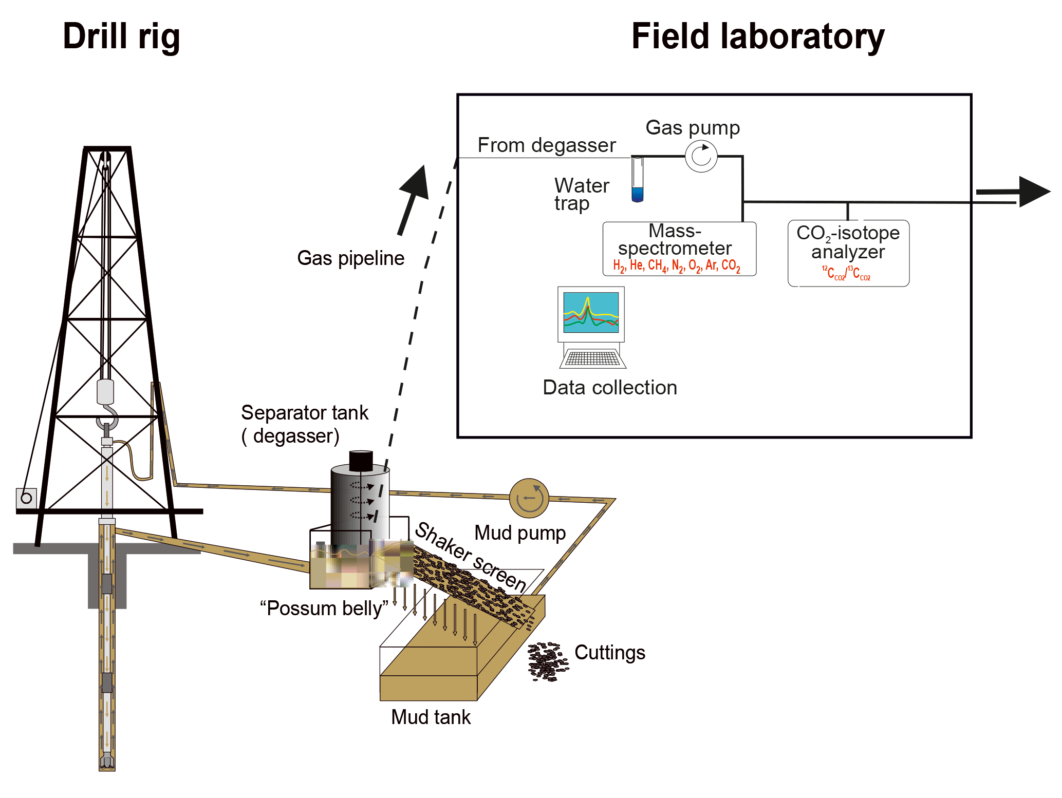
Figure 2Experimental setup of the mud gas extraction system and the field laboratory during drilling the side tracks at Ktzi 203.
The liberated gases were pumped to a nearby field laboratory and analyzed qualitatively and quantitatively around the clock in real time using a gas mass spectrometer (Omnistar, Pfeiffer Vacuum, time resolution of measurement 1 min, detection limit approximately 1 ppmV). Using these devices the composition of the drill mud gas phase was continuously analyzed for the volumetric quantity of H2, He, CO2, Ar, N2, O2, CH4. A Los Gathos CO2-isotope analyzer was employed in the field to continuously analyze the isotopic ratio of the mud gas phase at one minute intervals. LGR's CO2-isotope analyzer provided measurements of with a standard deviation σ of ±1 ‰. For the correction of the internal instrument drift a standard gas (ambient air; ‰) was measured automatically every 6 hours using a multiport inlet unit.
The core barrels retrieved at the surface were cut into 1 m sections and then shrink-wrapped with plastic foil to collect potentially discharging gas from the rock material within the first hour. After a degassing period of at least two hours, an injection needle mounted to the mass spectrometer inlet capillary was inserted through the wrapping foil. This procedure allowed for the direct determination of the trapped core gas with a mass spectrometer. Furthermore, core gas samples were collected for 13C∕12C-analyses of the CO2. For this purpose, a further needle was inserted through the wrapping. This needle was connected to a hose that linked via another needle to a borosilicate glass vial (i.e. Exetainer®) with a butyl-rubber septum. The gas was then transferred to the Exetainer using a syringe inserted into the same Exetainer via the septum. In this way 40 mL of sampling gas were sucked through the 12 mL vial resulting in a 3-times replacement with sample gas.
The analyses of the Exetainer gas were performed at the GFZ laboratories using a system consisting of a gas chromatograph (GC 6890N, Agilent Technology) connected to a GC-C/TC III combustion device coupled via open split to a MAT 253 mass spectrometer (ThermoFisher Scientific). The gas samples were injected with a gas-tight syringe into the programmable temperature vaporization inlet (PTV, Agilent Technology) of the GC which separated the gases on a PoraPlot column. Helium carrier gas transferred the CO2 to the mass spectrometer for determination of the carbon isotope ratios. The standard deviation σ for the isotopic measurements was ±0.5 ‰. The were reported in ‰ vs. VPDB (Vienna Pee Dee Belemnite).
Analyses of the core and mud gas phase from the side track drilling in 2017 revealed atmospheric concentrations of O2, N2, Ar, He, but higher concentrations for CO2. Both side tracks overlap at the depth section between 643 and 654.5 m. In this section the CO2 concentrations for both side tracks showed similar concentration-depth trends but at different concentration levels. The CO2 concentration in side track-a was generally about 2500 ppmV higher than in side track-b (Fig. 3).
Samples from the muddy cap rock section showed CO2 concentrations of about 500 ppmV. This rose drastically to values of up to 12 000 ppmV at the lithological transition to the reservoir sandstone of the Stuttgart formation due to the presence of injected CO2 in the pore space and decreased again to about 1000 ppmV in a muddy to silty layer (648–655 m) with lower porosity. In the sandstone section below 655 m (side track-a) CO2 concentrations of only up to 11 000 ppmV were measured. Therefore, the mud gas CO2 values of 2017 were significantly lower than the concentrations from core gas collected during drilling of the main hole in 2012 with maximum CO2 values of up to 99 vol. %. But generally both data series revealed the same depth trend.
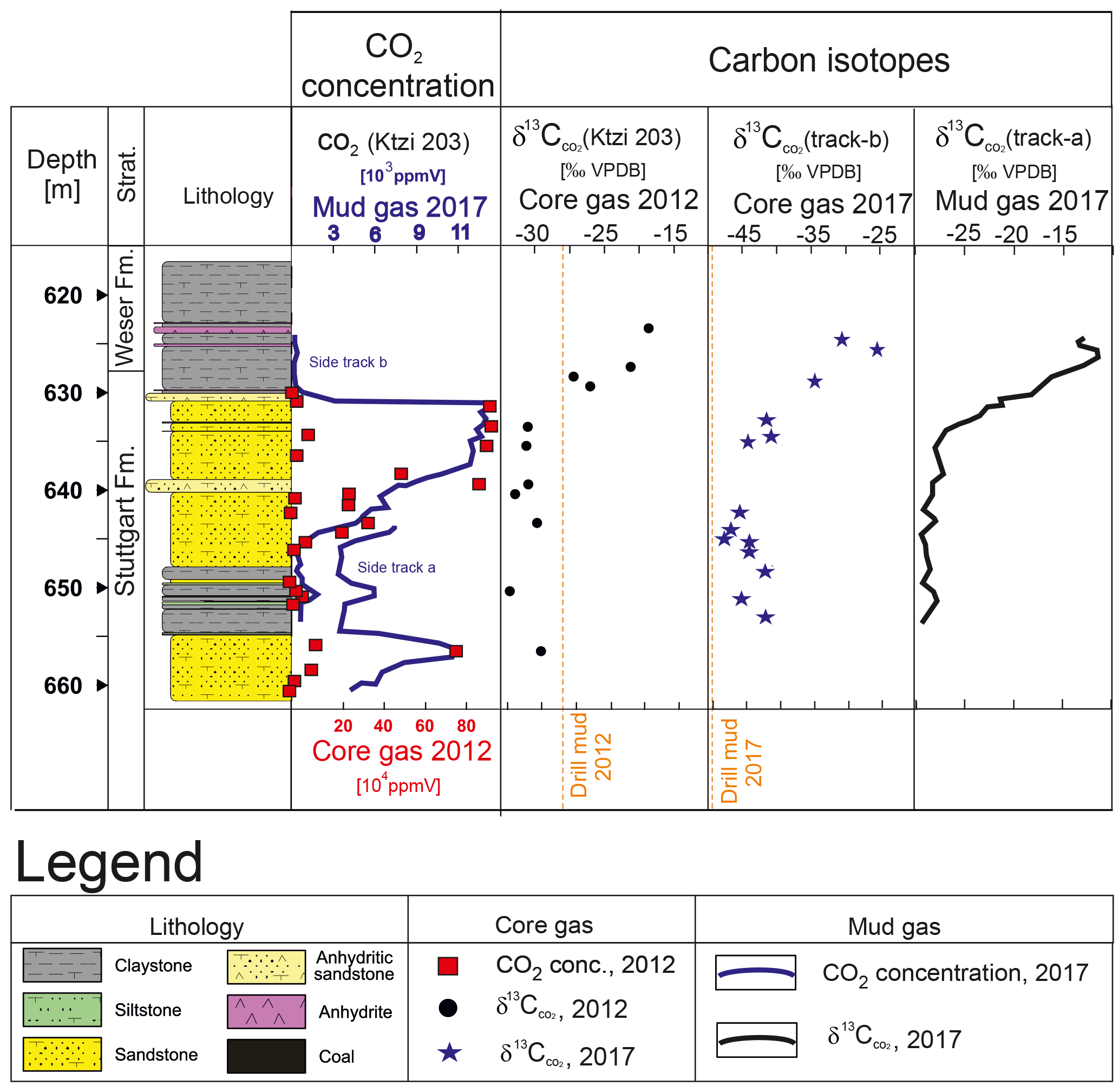
Figure 3Lithological profile and measured CO2 concentration in the mud gas of side track-a and -b as well as its from mud and core gas (side track-b). For comparison the CO2 concentration and the of core gas from 2012 is given. Squares, dots and stars represent analyses of single samples. Lines are continuous measurements at five-minute intervals.
Only isotope analyses of the core and the mud gas from side track-b were used for a comparison with previous core gas data presented by Barth et al. (2015) for the coring of Ktzi 203 main hole in 2012 (both using potash drill mud). Core and mud gas samples from the cap rock showed isotope values ranging from −25 to −35 and −10 to −20 ‰, respectively. The isotope values of the CO2 in the reservoir below a depth of 630 m were significantly different varying by around −45 ‰ in the core gas and by −28 ‰ in the mud gas phase. Generally, the isotope data of 2017 showed the same depth-trend as of core gas detected in 2012. Merely the variation range was different in 2012 from −18.6 ‰ in the cap rock to −36.6 ‰ in the reservoir (Barth et al., 2015).
Due to the applied methods and the unknown total amount of drill core degassing only semi-quantitative statements on occurring CO2 are possible. The detected CO2-concentrations-depth trend and the signatures during the side track drilling clearly indicate the injected CO2 in the reservoir horizon. As in 2012, the CO2 concentration drastically increases at the lithological intersection between the cap rock and the reservoir sandstone. The highest CO2 concentrations were measured in the top layer of the reservoir sandstones where most of the CO2 dispersed during the injection process (Kiessling et al., 2010). As the density of CO2 under the prevailing conditions is significantly lower than that of water, an upward migration of free CO2 within the reservoir formation can be expected.
Differences in the CO2 concentration of mud gas from side track-a and side track-b can be explained by the use of different drilling muds. Track-a was drilled with “Sole-fluid” containing mainly Na+ (97 g L−1) and Cl− (146 g L−1) at a pH of 7, whereas side track-b was drilled with a potash-drilling mud (K+ = 56 g L−1, CO 45 g L−1) at a pH between 10 and 11. As the CO2 is controlled by H3O+ activity of the applied drilling mud and by carbonate precipitation, where with decreasing pH of the mud the CO2 content in the gas phase increases (Zimmer and Erzinger, 1995), generally higher CO2 concentrations were expected at side track-a. The more depleted of the core gas compared to mud gas can be explained by a strong influence of the alkaline potash drill mud with a of −50 ‰ as described by Nowak et al. (2013). The CO2 in the cores was trapped together with the drill mud in plastic foil for several hours whereas the mud gas had contact with the drill mud for several minutes only during the lag time. As the drill mud gas was less influenced by the drilling mud, we assume that these data better represent the pristine isotope composition of the CO2 in the geological formations.
The isotope values from the cap rock samples of −10 to −20 ‰ cover the range of typical Triassic formation fluids in the North German Basin (Möller et al., 2008) and give no indication of an infiltration of injected CO2 with an average of ‰ (Barth et al., 2015). In contrast, the isotope values from the reservoir samples with on average −28 ‰ indicate the presence of the injected CO2 in the sandstone formation.
The CO2-concentrations and isotope signatures of the core and mud gas from 2017 show very similar depth profiles as compared with data from 2012. This result indicates that during the period of five years no significant movement of the CO2 in the formation had occurred. The low CO2 concentration in the cap rock and its isotopic composition suggests that the penetration of injected CO2 into the Weser formation was insignificant.
Gas-chemical and isotope investigation are direct methods for gaining chemical and physicochemical insights into CO2 behavior in the storage reservoir at the Ketzin pilot test site. The geochemical monitoring of CO2 has a high vertical resolution and allows for very sensitive detection of dissolved CO2. However, determination of gas-chemical parameters from deep formation is not trivial and boreholes represent the only possibility to gain direct information on the gas contents at depth. Furthermore, the gas samples collected while drilling are strongly influenced by technical conditions e.g. reaction with drill mud, partially degassing of cores or contamination with air. Despite these difficulties the concept for on-line determination of gases dissolved in the drilling mud and the core gas analyses, outlined and realized during this project, has proven to be successful. At the Ketzin pilot test site the side core drilling provided the sole opportunity to analyze gas samples from a depth interval in constant contact with injected CO2 for more than nine years and to compare these measurements with data collected five years earlier from the same depth section. In addition, it was possible to monitor the CO2 concentration and isotopic composition within the transition zone between cap and reservoir rocks. CO2 concentrations in the cap rock were low and their isotopic composition in accord with typical Upper Triassic formation fluids. A clear increase in the CO2 concentration and a shift in between the cap rock and the reservoir section indicated the presence of the injected CO2 in the reservoir and did not provide any evidence for a significant CO2 infiltration from the underlying reservoir into the cap rock. The comparison with samples collected five years earlier in 2012 showed similar concentration and isotopic depth trends which indicated a rather stagnant CO2 plume at depth suggesting the tightness and integrity of the cap rock and borehole cementation. This work focused only on a single well and a limited time period. Therefore, statements on the tightness can, for the present, only be made for the cap rock, cement and casing material in the immediate vicinity of well Ktzi 203. Final conclusions on the long-term behavior of CO2 in the underground, especially along fracture zones cannot be drawn.
The data will be accessible after publication in the data repository of the GFZ at: http://gfzpublic.gfz-potsdam.de/pubman/.
Andreas Jurczyk (Helmholtz-Centre Potsdam – GFZ German Research Centre for Geosciences, Telegrafenberg, 14473 Potsdam, Germany), Christian Kujawa (Helmholtz-Centre Potsdam – GFZ German Research Centre for Geosciences, Telegrafenberg, 14473 Potsdam, Germany), Cornelia Schmidt-Hattenberger (Helmholtz-Centre Potsdam – GFZ German Research Centre for Geosciences, Telegrafenberg, 14473 Potsdam, Germany), Stefan Lüth (Helmholtz-Centre Potsdam – GFZ German Research Centre for Geosciences, Telegrafenberg, 14473 Potsdam, Germany), Fabian Möller (Helmholtz-Centre Potsdam – GFZ German Research Centre for Geosciences, Telegrafenberg, 14473 Potsdam, Germany)
The authors declare that they have no conflict of interest.
This article is part of the special issue “European Geosciences Union General Assembly 2018, EGU Division Energy, Resources & Environment (ERE)”. It is a result of the EGU General Assembly 2018, Vienna, Austria, 8–13 April 2018.
The authors gratefully acknowledge the interdisciplinary team working on the
Ketzin project. The authors highly appreciate the funding for the Ketzin
project received from the European Commission (6th and 7th Framework
Program), the German Federal Ministry of Economics and Technology and the
German Federal Ministry of Education and Research. Further funding was
received from VGS, RWE, Vattenfall, Statoil, OMV and the Norwegian CLIMIT
program. We thank Mary Teresa Lavin-Zimmer for her valuable comments on this
manuscript.
The article processing charges for this open-access
publication
were covered by a Research
Centre of the Helmholtz Association.
Edited by: Luke Griffiths
Reviewed by: two anonymous referees
Barth, J. A. C., Nowak, M. E., Zimmer, M., Norden, B., and van Geldern, R.: Monitoring of cap rock integrity during CCS from field data at the Ketzin pilot site (Germany): Evidence from gas composition and stable carbon isotopes, Int. J. Greenh. Gas Con., 43, 133–140, 2015.
Förster, A., Norden, B., Zinck Jørgensens, K., Frykman, P., Kulenkampff, J., Spangenberg, E., Erzinger, J., Zimmer, M., Kopp, J., Borm, G., Juhlin, C., Cosma, C., and Hurter, S.: Baseline characterization of the CO2SINK geological storage site at Ketzin, Germany, Environ. Geosci., 13, 145–161, 2006.
Giese, R., Henninges, J., Lüth, S., Morozova, D., Schmidt-Hattenberger, C., Würdemann, H., Zimmer, M., Cosma, C., Juhlin, C., and CO2SINK Group: Monitoring at the CO2SINK Site: A Concept Integrating Geophysics, Geochemistry and Microbiology, Energy Proced., 1, 2251–2259, 2009.
Kiessling, D., Schmidt-Hattenberger, C., Schuett, H., Schilling, F., Krueger, K., Schoebel, B., Danckwardt, E., Kummerow, J., and the CO2SINK Group: Geoelectrical methods for monitoring geological CO2 storage: First results from cross-hole and surface-downhole measurements from the CO2SINK test site at Ketzin (Germany), Int. J. Greenh. Gas Con., 4, 816–826, 2010.
Martens, S., Liebscher, A., Möller, F., Henninges, J., Kempka, T., Lüth, S., Norden, B., Prevedel, B., Szizybalski, A., Zimmer, M., Kühn, M., and the Ketzin Group: CO2 storage at the Ketzin pilot site, Germany: Fourth year of injection, monitoring, modelling and verification, Energy Proced., 37, 6434–6443, 2013.
Martens, S., Möller, F., Streibel, M., Liebscher, A., and the Ketzin Group: Completion of five years of safe CO2 injection and transition to the post-closure phase at the Ketzin pilot site, Energy Proced., 59, 190–197, 2014.
Möller, P., Weise, S. M., Tesmer, M., Dulski, P., Pekdeger, A., Bayer, U., and Magri, F.: Salinization of groundwater in the North German Basin: results from conjoint investigation of major, trace element and multi-isotope distribution, Int. J. Earth Sci., 97, 1057–1073, 2008.
Nowak, M., Myrtinnen, A., Zimmer, M., Wiese, B., van Geldern, R., and Barth, J. A. C.: Well-based, geochemical leakage monitoring of an aquifer immediately above a CO2 storage reservoir by stable carbon isotopes at the Ketzin pilot site, Germany, Energy Proced., 40, 346–354, 2013.
Wipki, M., Ivanova, A., Liebscher, A., Lüth, S., Möller, F., Szizybalski, A., Wiese, B., and Zimmer, M.: Monitoring Concept for CO2 Storage at the Ketzin Pilot Site,Germany – post-injection continuation towards transfer of liability, Energy Proced., 97, 348–355, 2016.
Zimmer, M. and Erzinger, J.: On the geochemistry of gases in formation and drilling fluids – results from KTB, Scientific drilling, 5, 101–109, 1995.