 | 02 Aug 2018
Preliminary study on geo-mechanical aspects of SSiC canisters
Ya-Nan Zhao
Heinz Konietzky
Jürgen Knorr
Albert Kerber
To meet safety requirements for underground storage of high-level nuclear waste, engineered barriers are an integral part of a modern defense-in-depth concept and therefore have to be considered in interaction with the host rock. This study presents preliminary results for the load behavior of a canister made of pressure-less sintered silicon carbide (SSiC), which forms the main retention barrier for the fission products in a new multi-layer waste package design denominated as TRIPLE C. This means a three-fold enclosure strategy, spreading the functionalities to three different ceramic barriers: first the porous potting compound surrounding each single fuel rod in the container, second the solid container wall of SSiC and third the over-pack of carbon concrete. Besides all the advantages a potential drawback of ceramics in general is their brittleness. Therefore, the behavior of SSiC structural components under static and dynamic loading has to be investigated. First results for a small model canister indicate that static loading will not create any relevant damage, even if stresses are extremely high and highly anisotropic on a canister all-around embedded. First dynamic simulations indicate that, under very unfavorable circumstances, the model canister can experience tensile stresses bigger than its tensile strength. Also, point loading may cause damage to the canister under certain conditions. Based on the performed calculations, the SSiC canister design will be optimized together with the carbon concrete over-pack, so that mechanical damage of main retention barrier can be excluded even under extreme static and dynamic conditions in a final repository.


1.1 General characteristics of SSiC
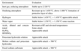
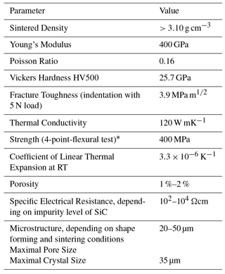
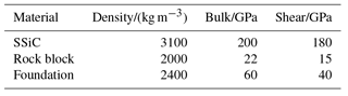
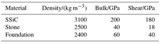
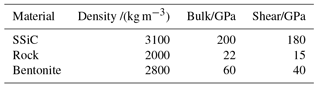
Sintered Silicon Carbide (SSiC) is a material characterized by high corrosion resistance, gas-tightness, extreme long-term stability (Peterson and Dunzik-Gougar, 2011; Mceachern et al., 2012) and high temperature resistance. The exceptional corrosion resistance against several relevant agents is well known and listed in Table 1. Further parameters for SSiC with boron and carbon as sintering aids are given in Table 2.
1.2 Microstructure of SSiC
Figure 1 shows the microstructure of a polished cross section of SSiC. The surface is relatively smooth with very small micro pores, mostly below 10 µm. No big pores are observed. Figure 2 shows a fracture surface of SSiC. The SSiC has very small crystals (about 1 µm mean diameter) and the regular polyhedron-shaped crystals are relatively densely distributed.
1.3 Mechanical parameters
Holmquist et al. (1999) reported a static uniaxial compressive strength of around 3900 MPa of SiC-B (boron as additive) at room temperature. In fact their test results indicate that the static uniaxial compressive strength will remain relatively stable from −200 to 570 ∘C. Lee et al. (2005) reported static uniaxial compressive strength for SiC-N (a refined product of SiC-B that uses an organic binder) of 3872±126 MPa. Figure 3 illustrates the explosive-like failure of SiC-N (Lee et al., 2005) under uniaxial compression. Bassett et al. (1993) measured maximum pressure of 68 GPa by confining the SiC material in a mixture of sodium chloride and gold, methanol, ethanol and water, respectively, to produce a hydrostatic pressure environment (Dandekar, 2002). Yoshida et al. (1993) has obtained a maximum pressure of 95 GPa with a similar method. Lee et al. (2005) have performed triaxial compression tests on SiC Fig. 4 shows corresponding stress-strain curves. A shear failure criterion is proposed in that paper.
Table 2Material parameter of SSiC (SiCeram GmbH, 2012).
∗ The component strength depends on geometry (According to the Griffith, 1924, theory of rupture a defect size of 50 µm results in a strength of ca. 400 MPa at the intrinsic fracture toughness of SSiC of 3.9 MPa m1∕2.).
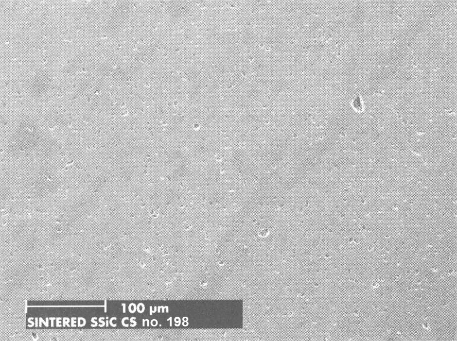
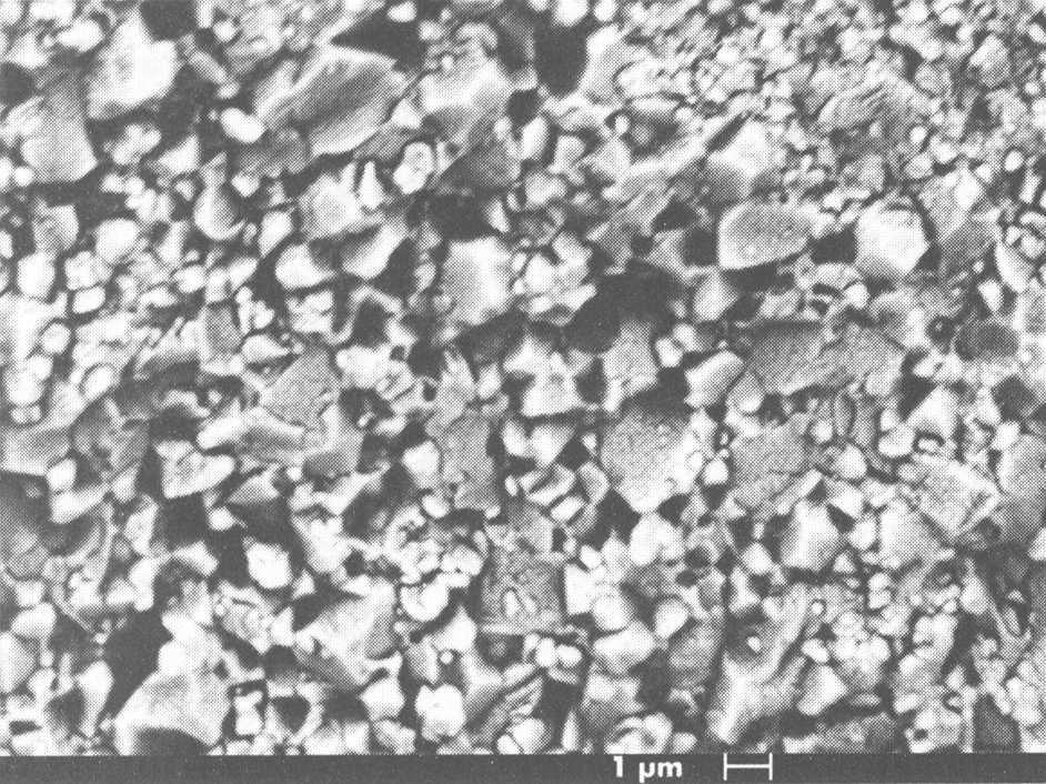
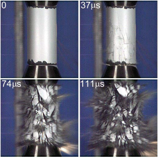
Figure 3Explosive failure of the SiC-N specimen (12.7 mm in diameter and 25.4 mm in length) subjected to unconfined uniaxial compression (σ1=3988 MPa at failure) (Lee et al., 2005).
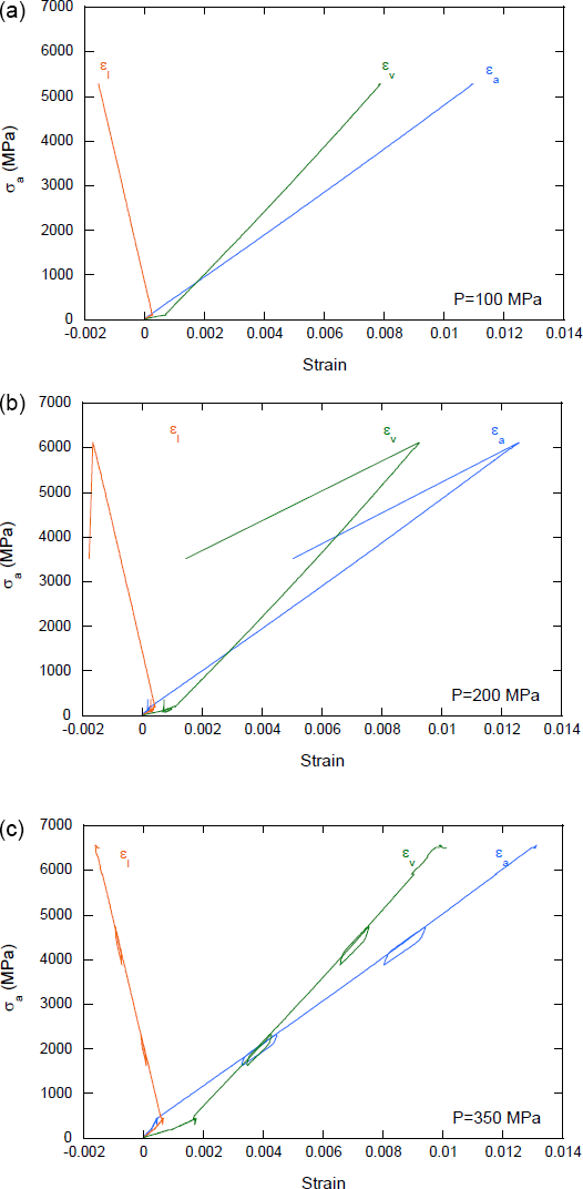
Figure 4Triaxial stress-strain curves at different confining pressures P=100 MPa (a), 200 MPa (b), and 350 MPa (c); εl: circumferential, εv: volumetric, εa: axial (Lee et al., 2005).
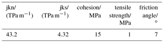
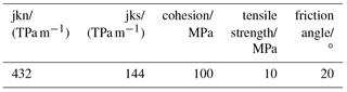
Additional mechanical testing was performed to investigate the strength characteristics in detail under consideration of the relevant potential loading situations. Line failure load of SSiC ring is determined by lab tests, numerical simulations and an analytical solution are also given. A line load applied to a hollow cylinder can be considered as an extreme, but also realistic loading scenario. The tests were performed on 5 cm long specimen with outer and inner diameter of 2.5 and 2 cm, respectively. Tables 3 and 4 give information of constitutive parameters for matrix and interfaces. For comparison, lab test and numerical simulation results are plotted in Fig. 5. The sharp decrease in load implies this material is very brittle and generates almost no plastic strain before failure. Colored lines No. 1 to 5 show lab test results. The black and orange dashed line represent the simulation result in form of the force-displacement curve when tensile strength of SSiC is 150 and 200 MPa, respectively. These simulations verify in comparison with the lab test results that tensile strength of specimen is between 150 and 200 MPa. Tables 1 and 2 contain the model parameters for the simulations. A strain-softening model is applied. Bulk and shear modulus are set to 200 and 180 GPa, respectively, according to literature (Dandekar, 2002; Holmquist et al., 1999). The cohesion was deduced from a test with similar material SiC-N and set to 4 GPa (Lee et al., 2005). Figure 6a shows the onset of tensile failure zone along the inner radius opposite to the loading line (T is tensile strength in strain-softening model). Figure 6b shows the post-failure maximum principle stress distribution. The tensile stress generated along inner surface of most upper part of the cylinder never exceeds 150 MPa. The cylinder fails abruptly according to Fig. 5.
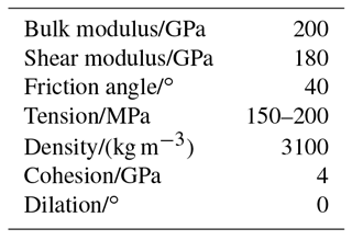
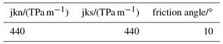
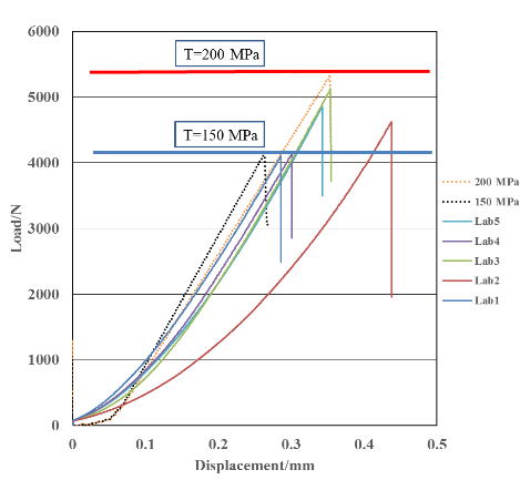
Figure 5Lab and numerical simulation results for line load test on hollow cylinder according to Fig. 6 (loading rate 0.004 mm s−1).
Available analytical solutions can be useful to predict the stress state inside the waste canisters with hollow cylinder shape under simplified boundary conditions, like constant static circumferential pressure or constant static line load.
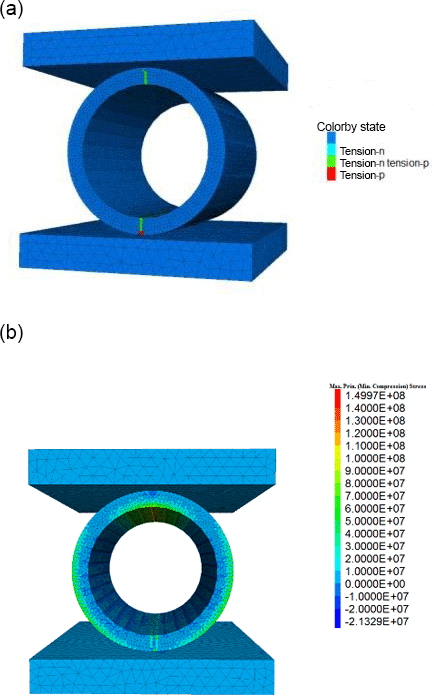
Figure 6(a) Onset of tensile failure (T=150 MPa). (b) Post failure maximum principal stress [Pa] (T=150 MPa).
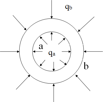
Lame's solution for the hollow cylinder under radial inner and outer pressure can be used to predict the stress state under hydrostatic confinement. The inner radius is given by a, the outer radius by b, the corresponding radial pressures are qa and qb (Fig 7).
Lamé solutions is given by Eqs. (1) and (2):
where σr and σθ are the radial and tangential (circumferential) principal stresses, respectively.
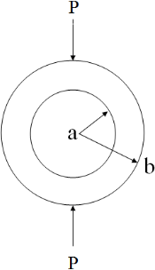
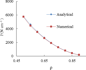
Figure 9Analytical and numerical results for failure load P vs. radius ratio assuming tensile strength of 150 MPa.
Under assumption that inner radial pressure qa is zero the maximum tensile stress σθ is recorded at the inner wall (r=a) and given by Eq. (3).
Timoshenko's solution according to Fig. 8 and Eq. (4) can be used to predict critical stress in a hollow cylinder under compressive line load. Failure line load P is determined by tensile strength σθ, outer radius R, as well as radius ratio . A tensile strength of 150 MPa is used for the presented calculation according to the lab tests. Figure 9 shows the analytical solution in comparison to the numerical solution of the failure load for various radius ratio when the tensile strength is set to 150 MPa.
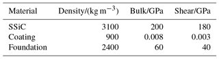
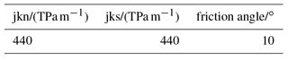
Table 6Constitutive parameters for interface between canister and foundation.
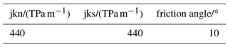

Figure 10(a) Initial maximum principal stress [Pa]. (b) Maximum principle stress [Pa] during impact. (c) Maximum principal stress [Pa] (canister with coating).
The stability of SSiC canisters under extreme loading conditions is investigated by several numerical models. Firstly, free fall is considered; secondly, an impact caused by roof fall and thirdly, impact by point loading. The last calculation case considers a highly anisotropic in-situ stress field acting on the canister surface. The simulations were performed using the distinct element code 3DEC (Itasca, 2016).
3.1 Drop from 2 m height
This simulation considers accident fall from a height of 2 m. The height of 2 m takes into account the actual height of transport vehicles and the design of underground openings. The canister has inner and outer radius of 0.10 and 0.12 m, respectively. The length is 0.5 m. The parameters of SSiC canister, rock mass as well as protection coating are listed in Tables 5 and 6. Viscous boundaries for the foundation and zero damping are applied.
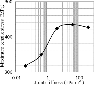
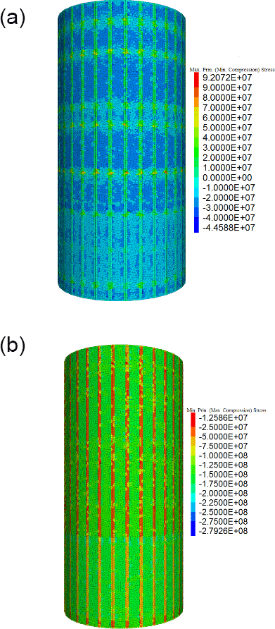
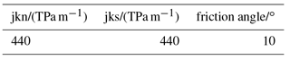
Simulation results are shown in Fig. 10. Under the mentioned circumstances and a tensile strength of 150 MPa the canister will locally fail. To avoid this, either the thickness of the canister wall has to be increased or a soft coating (protection layer) around the outer surface of the canister is needed to absorb kinetic energy. For simplicity, an elastic coating with no damping is assumed. The coating layer has a thickness of 40 mm and is much softer than SSiC. This results in significant reduced maximum tensile stress (about 83 MPa) within the canister. It would be even lower considering plasticity and damping. An interface stiffness of 440 TPa m−1 is used for the simulations as documented in Fig. 10. Since the interface properties under dynamic loading are unknown, a huge range from 0.044 to 440 TPa m−1 was selected for the simulations. Nevertheless, without coating any condition results in local maximum tensile stresses above 150 MPa as shown in Fig. 11.
3.2 Impact from falling rock
Figure 12 shows the general model set-up. The canister has inner and outer radius of 0.10 and 0.12 m respectively, and a length of 0.5 m. The falling rock block (cuboid) has edge length of mm. Falling height is 2 m, but considering the height occupied by the foundation, the actual acceleration height is about 1.5 m. Uniaxial compressive strength of the rock mass can vary from 0.1 to more than 100 MPa, depending on the type of rock considered in disposal area. In this simulation, the rock is composed of mineral grains represented by small discrete blocks connecting with each other (grain-scale contact parameters calibrated, uniaxial compressive strength 21.8 MPa, Young's modulus 14 GPa, Poisson's ratio 0.43, Liu et al., 1999; Crystran, 2012; Mikhalyuk et al., 1998; Zhao and Wan, 2010). Viscous boundaries for foundation are used. Damping is set to zero. Table 7 shows the model parameters. Table 8 gives calibrated grain-scale contact parameters. Table 9 gives parameters for interfaces for the discrete element model.
It is seen from Fig. 13 that maximum tensile stress induced by a 7.5 kg falling rock block can go up to 112 MPa. For comparison, a pure elastic continuum-based model shows maximum tensile stress is 324 MPa (Fig. 14a), much bigger than the 112 MPa predicted by the discrete element model. Stiffer rocks like granite should induce bigger tensile stress. Under another extreme condition – the rock is a 6.0 kg tetrahedron which has point-line contact with the canister (Fig. 14b) – the maximum tensile stress along inner surface of canister never exceeds 20 MPa, and the tensile stress in the direct contact area reaches only about 33 MPa. The rock tip will break first especially when the rock is less stiff. Anyway, coating is needed.
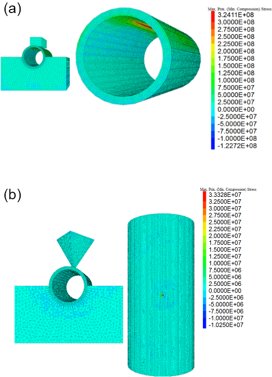
Figure 14(a) Maximum principle stress [Pa] (pure elastic). (b) Maximum principle stress [Pa] (dynamic point impact).

3.3 Impact by static point loading
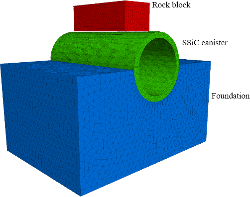
Figure 15 shows the chosen geometry to study the impact of static point load: a small stone is placed between foundation and SSiC canister, creating a point load on the SSiC canister. The foundation is fixed vertically and the canister experiences an additional line load of 10 MPa along the canister roof. The canister has inner and outer radius of 0.10 and 0.12 m respectively, and a length of 0.5 m. Tables 10, 11 and 12 show the model parameters. Grain-scale contact parameters are calibrated and the uniaxial compressive strength is around 200 MPa. The stone has edge length of mm. As Fig. 16 suggests the canister will fail when subjected to such uneven loading condition.
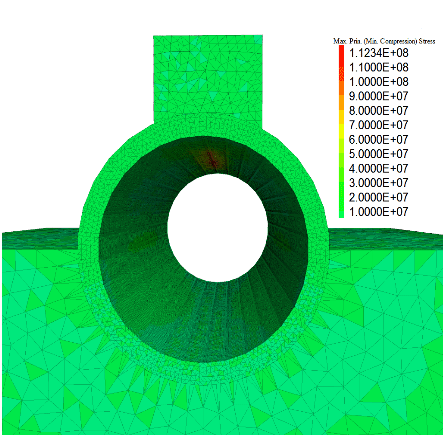
3.4 Embedded canister in highly anisotropic stress field
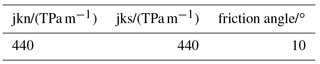
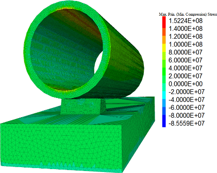
This model assumes that the SSiC canister is protected by a layer of compacted bentonite (8 cm thick), embedded in the rock mass which is characterized by a vertical stress component of 10 MPa and a horizontal principal stress of 30 MPa. The canister has inner and outer radius of 0.10 and 0.12 m respectively, and a length of 0.5 m. Rock mass, bentonite and canister are elastic. Bentonite will generate swelling pressure of 30 MPa itself due to water absorption. The selected region is m3 considering the diameter of canister is just 0.24 m (Fig. 17). It is assumed that no significant displacement occurs around the shaft. The modeling strategy is to replace the excavated rock mass with swelling bentonite and the SSiC canister.
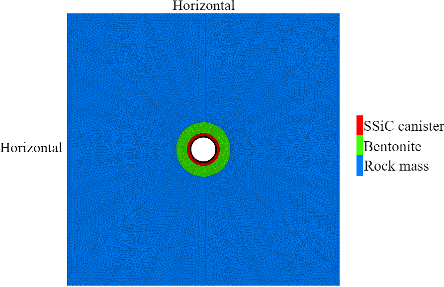
Figure 18 shows the model set-up. Tables 13 and 14 list parameters for matrix and interface. Figure 18 shows that the canister experiences compressive stress of 279 MPa and tensile stress of about 92 MPa under combined loading from earth and swelling pressure (first and second principle stress 30 MPa, third principle stress 10 MPa, swelling pressure 30 MPa).
SSiC material is brittle but with very high tensile strength (150–200 MPa). First results for a small model canister indicate that static loading will not create any relevant damage on a canister all-around embedded, even if stresses are extremely high and highly anisotropic. Point loading, under very unfavorable conditions, will damage the bare SSiC canister. But once more the canister sustains even a highly anisotropic stress field if all-around embedded as an effective countermeasure. The performed calculations underline the concept that the SSiC canister alone sustains definite loading of the host rock, but should be protected generally by a mechanically robust over-pack preferably made of carbon concrete to complete a final waste package for all types of host rocks (shared and split functionality in TRIPLE C concept; Kerber and Knorr, 2017). To avoid any failure, the procedure of SSiC has to guarantee a certain limit of microdefects.
No data sets were used in this article.
YNZ has provided some ideas for simulation and performed all simulations. HK has provided some ideas for simulation and helped to fix simulation issues. AK and JK have provided the SSiC material for experiment and data relating to physical characterization of SSiC.
The authors declare that they have no conflict of interest.
This article is part of the special issue “European Geosciences
Union General Assembly 2018, EGU Division Energy, Resources & Environment
(ERE)”. It is a result of the EGU General Assembly 2018, Vienna, Austria,
8–13 April 2018.
Edited by: Michael Kühn
Reviewed by: two anonymous referees
Bassett, W. A., Weathers, M. S., and Wu, T. C.: Compressibility of SiC up to 68.4 GPa, J. Appl. Phys., 74, 3824, https://doi.org/10.1063/1.354476, 1993.
Crystran: Sodium Chloride (NaCl), available at: https://www.crystran.co.uk/optical-materials/sodium-chloride-nacl (last access: 24 July 2018), 2012.
Dandekar, D. P.: A Survey of Compression Studies of Silicon Carbide (SiC), ARL-TR-2695, U.S. Army Research Laboratory, Aberdeen Proving Ground, MD, USA, 2002.
Griffith, A. A.: The theory of rupture, Proc. 1st Internat. Congr. Appl. Mech., Delft, the Netherlands, 55–63, 1924.
Holmquist, T. J., Rajendran, A. M., Templeton, D. W., and Bishnoi, K. D.: A Ceramics Armor Material Database, TARDEC Technical Report, TRADEC, USA, January, 1999.
Itasca: 3DEC Manuals, Itasca Consulting Group, Minneapolis, Minnesota, USA, 2016.
Kerber, A. and Knorr, J.: Full-ceramic, multi-barrier TRIPLE C waste package for disposal of radionuclides and other hazardous materials in crystalline, clay or salt host rock, list of publications, no. 6, available at: http://www.ceramics-for-nuclear.info (last access: 24 July 2018), 2017.
Lay, L. A.: Corrosion Resistance of Technical Ceramics, National Physical Laboratory, Teddington, Middlesex, UK, Pub H.M.S.O., 1983.
Lee, M. Y., Brannon, R. M., and Bronowski, D. R.: Uniaxial and Triaxial Compression Tests of Silicon Carbide Ceramics under Quasi-static Loading Condition, SANDIA REPORT, Sandia National Laboratories, Albuquerque, New Mexico, USA, 2005.
Liu, X. R., Jiang, D. Y., Yu, H., and Ma, J. C.: The Experiment Study of Rocksalt's Deformation Characteristics, Mining and Metallurgical Engineering, 4, 12–15, 1999.
Mceachern, D. W., Wu, W., and Venneri, F.: Performance of PyC, SiC, ZrC coatings in the geologic repository, Nucl. Eng. Des., 251, 102–110, https://doi.org/10.1016/j.nucengdes.2011.10.065, 2012.
Mikhalyuk, A. V., Zakharov, V. V., and Parshukov, P. A.: Rocksalt under nonequilibrium dynamic loads, J. Min. Sci., 34, 1–9, https://doi.org/10.1007/BF02765518, 1998.
Peterson, J. L. and Dunzik-Gougar, M. L.: Modeling spent TRISO fuel for geological disposal: corrosion and failure under oxidizing conditions in the presence of water, Prog. Nucl. Energ., 53, 278–284, https://doi.org/10.1016/j.pnucene.2010.12.003, 2011.
SiCeram GmbH: Technical Data Sheet, SiC, Jena, Germany, 2012.
Yoshida, M., Onodera, A., Ueno, M., Takemura, K., and Shimomura, O.: Pressure-Induced Phase Transition in SiC, Phys. Rev. B., 48, 10587–10590, https://doi.org/10.1103/PhysRevB.48.10587, 1993.
Zhao, Y. L. and Wan, W.: Mechanical Properties of Bedded Rock Salt, EJGE, 19, 9347–9353, 2014.